3. 动态转矩补偿(加减速)
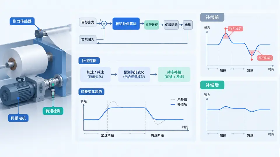
任务定义
在卷绕/放卷张力控制系统中,当设备进行加减速时,由于惯性负载的存在,实际张力会偏离设定值。本案例实现一个动态转矩补偿算法,根据实时加速度和系统转动惯量计算补偿转矩,叠加到静态张力转矩指令上,使加减速过程中张力保持稳定。
核心原理
张力控制的基本方程为:Tmotor = Ttension + J·α,其中Ttension为维持设定张力所需的转矩,J为卷轴及料卷的等效转动惯量,α为角加速度。动态补偿的目标就是实时计算J·α项并叠加到输出转矩上。由于卷径变化导致J变化,本案例采用实时卷径跟踪方式更新J值。
代码实现
// dynamic_torque_compensation.c
#include <stdio.h>
#include <math.h>
#define PI 3.14159265f
#define DT 0.001f // 控制周期 1ms
// 系统参数
typedef struct {
float J_core; // 空卷轴惯量 (kg·m²)
float rho; // 材料密度 (kg/m³)
float width; // 材料宽度 (m)
float gear_ratio; // 电机到卷轴减速比
float max_accel; // 最大允许加速度 (rad/s²)
} SystemParam;
// 运行状态
typedef struct {
float speed; // 当前线速度 (m/s)
float prev_speed; // 上一周期线速度 (m/s)
float radius; // 当前卷径 (m)
float tension_set; // 设定张力 (N)
float torque_out; // 最终输出转矩 (N·m)
} DriveState;
// 计算当前卷径(基于线速度与角速度关系)
float calc_radius(float line_speed, float angular_speed) {
if (fabsf(angular_speed) < 0.01f) return 0.1f; // 防止除零
return line_speed / angular_speed;
}
// 计算等效转动惯量(卷轴+料卷)
float calc_inertia(SystemParam *param, float radius) {
float J_material = 0.5f * param->rho * param->width * PI *
(powf(radius, 4) - powf(0.05f, 4));
// 折算到电机轴
return (param->J_core + J_material) / (param->gear_ratio * param->gear_ratio);
}
// 动态转矩补偿主函数
float dynamic_compensation(SystemParam *param, DriveState *state,
float angular_speed, float line_speed) {
// 1. 更新卷径
state->radius = calc_radius(line_speed, angular_speed);
if (state->radius < 0.05f) state->radius = 0.05f;
if (state->radius > 0.3f) state->radius = 0.3f;
// 2. 计算线加速度
float accel = (line_speed - state->prev_speed) / DT;
state->prev_speed = line_speed;
// 3. 加速度限幅(防止过大的补偿冲击)
if (accel > param->max_accel * state->radius)
accel = param->max_accel * state->radius;
if (accel < -param->max_accel * state->radius)
accel = -param->max_accel * state->radius;
// 4. 计算角加速度
float angular_accel = accel / state->radius;
// 5. 计算动态补偿转矩(折算到电机轴)
float J_total = calc_inertia(param, state->radius);
float torque_comp = J_total * angular_accel * param->gear_ratio;
// 6. 静态张力转矩
float torque_tension = state->tension_set * state->radius / param->gear_ratio;
// 7. 总输出转矩
state->torque_out = torque_tension + torque_comp;
return state->torque_out;
}
// 测试主函数
int main() {
SystemParam param = {
.J_core = 0.02f, // 空轴惯量
.rho = 900.0f, // 材料密度 kg/m³
.width = 0.1f, // 幅宽 100mm
.gear_ratio = 5.0f, // 减速比 5:1
.max_accel = 2.0f // 最大加速度 2 m/s²
};
DriveState state = {
.speed = 0.0f,
.prev_speed = 0.0f,
.radius = 0.1f, // 初始卷径 100mm
.tension_set = 50.0f, // 设定张力 50N
.torque_out = 0.0f
};
// 模拟加速过程:线速度从0加速到2m/s,持续1秒
printf("时间(s) 线速度(m/s) 卷径(m) 补偿转矩(N·m) 总转矩(N·m)\n");
for (int i = 0; i <= 1000; i++) {
float t = i * DT;
float target_speed = 2.0f * t; // 线性加速到2m/s
if (target_speed > 2.0f) target_speed = 2.0f;
// 模拟角速度(假设线速度与卷径匹配)
float angular_speed = target_speed / state.radius;
float torque = dynamic_compensation(¶m, &state,
angular_speed, target_speed);
if (i % 100 == 0) {
float torque_comp = torque - state.tension_set * state.radius / param.gear_ratio;
printf("%.3f %.3f %.3f %.3f %.3f\n",
t, target_speed, state.radius, torque_comp, torque);
}
}
return 0;
}
关键逻辑说明
代码中dynamic_compensation()函数实现了完整的补偿算法:首先通过线速度和角速度实时计算当前卷径,然后基于卷径计算包含料卷在内的等效转动惯量。加速度通过线速度差分获得,并经过限幅处理防止补偿转矩突变。最终输出转矩为静态张力转矩与动态补偿转矩之和。主函数模拟了1秒内从静止加速到2m/s的过程,每100ms打印一次关键数据。
SVG:加减速动态补偿控制框图
编译与运行
gcc -o dynamic_torque dynamic_torque_compensation.c -lm
./dynamic_torque
验证方法
运行程序后观察输出:在加速阶段(0~1s),补偿转矩应为正值且随加速度增大而增大;当速度达到2m/s后加速度为零,补偿转矩应降为0,总转矩等于静态张力转矩。判定标准:
- 加速过程中总转矩 > 静态张力转矩,差值即为补偿量
- 匀速阶段补偿转矩趋近于0
- 卷径在加速过程中因线速度与角速度匹配而保持基本恒定
若需验证减速过程,可将主循环中目标速度改为递减函数,观察补偿转矩变为负值。