1. 基础门电路实现
任务目标
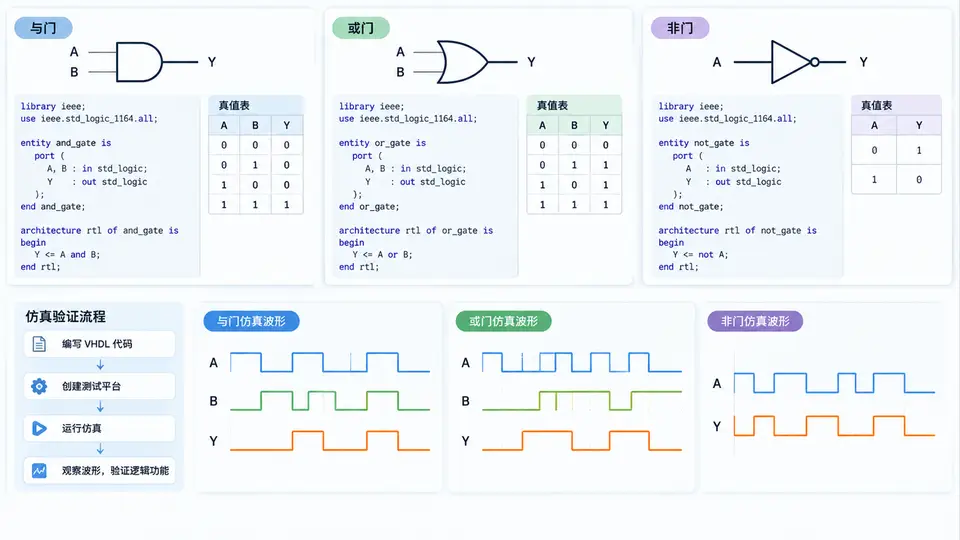
使用VHDL分别实现与门(AND)、或门(OR)、非门(NOT)三种基本逻辑门电路,并通过VHDL仿真验证其真值表逻辑功能是否正确。
环境依赖
本案例需要VHDL仿真工具,推荐使用GHDL(开源)或ModelSim。以下验证步骤以GHDL为例,需确保已安装GHDL。
完整VHDL实现
-- 文件: basic_gates.vhd
library ieee;
use ieee.std_logic_1164.all;

-- 与门实体
entity and_gate is
    port (
        a : in  std_logic;
        b : in  std_logic;
        y : out std_logic
    );
end entity;

architecture behavior of and_gate is
begin
    y <= a and b;
end architecture;

-- 或门实体
entity or_gate is
    port (
        a : in  std_logic;
        b : in  std_logic;
        y : out std_logic
    );
end entity;

architecture behavior of or_gate is
begin
    y <= a or b;
end architecture;

-- 非门实体
entity not_gate is
    port (
        a : in  std_logic;
        y : out std_logic
    );
end entity;

architecture behavior of not_gate is
begin
    y <= not a;
end architecture;
仿真测试平台
-- 文件: basic_gates_tb.vhd
library ieee;
use ieee.std_logic_1164.all;

entity basic_gates_tb is
end entity;

architecture sim of basic_gates_tb is
    signal a, b : std_logic;
    signal y_and, y_or : std_logic;
    signal y_not : std_logic;
begin
    -- 实例化被测模块
    uut_and : entity work.and_gate port map (a => a, b => b, y => y_and);
    uut_or  : entity work.or_gate  port map (a => a, b => b, y => y_or);
    uut_not : entity work.not_gate port map (a => a, y => y_not);

    -- 测试激励
    process
    begin
        -- 测试与门和或门(4种输入组合)
        a <= '0'; b <= '0'; wait for 10 ns;
        a <= '0'; b <= '1'; wait for 10 ns;
        a <= '1'; b <= '0'; wait for 10 ns;
        a <= '1'; b <= '1'; wait for 10 ns;

        -- 测试非门(2种输入)
        a <= '0'; wait for 10 ns;
        a <= '1'; wait for 10 ns;

        wait;  -- 结束仿真
    end process;
end architecture;
运行与验证步骤
- 分析编译:
ghdl -a basic_gates.vhd
ghdl -a basic_gates_tb.vhd - 运行仿真:
ghdl -r basic_gates_tb --vcd=result.vcd - 查看波形:
用GTKWave打开result.vcd文件,观察信号a、b、y_and、y_or、y_not的波形。
验证判定标准
在波形中检查以下逻辑关系,全部满足即验证通过:
- 与门:仅当a=1且b=1时,y_and=1;其余组合y_and=0。
- 或门:仅当a=0且b=0时,y_or=0;其余组合y_or=1。
- 非门:y_not始终等于a的反相(a=0时y_not=1,a=1时y_not=0)。
预期输出说明
根据代码逻辑可直接推出:仿真时间0-10ns期间(a=0,b=0),y_and=0、y_or=0、y_not=1;10-20ns期间(a=0,b=1),y_and=0、y_or=1、y_not=1;20-30ns期间(a=1,b=0),y_and=0、y_or=1、y_not=0;30-40ns期间(a=1,b=1),y_and=1、y_or=1、y_not=0。此结果与基本门电路真值表完全一致。