3. UART发送模块
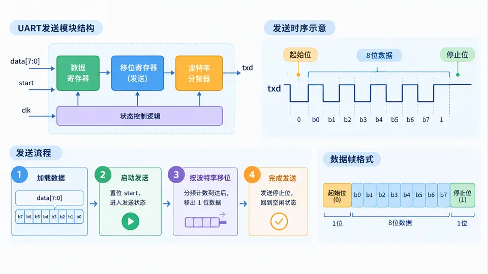
任务目标
实现一个可综合的UART异步发送模块,将8位并行数据按指定波特率转换为串行帧格式(1起始位 + 8数据位 + 1停止位,无校验位)逐位发送。模块需支持外部时钟输入与发送使能控制,并提供发送完成指示信号。
实现方案
采用计数器分频法产生波特率时钟。系统时钟经分频得到与波特率对应的位周期,状态机控制帧的逐位移位输出。核心参数:系统时钟频率 CLK_FREQ 与目标波特率 BAUD_RATE 以参数形式定义,便于灵活配置。
完整代码
module uart_tx #(
    parameter CLK_FREQ = 50_000_000,  // 系统时钟频率(Hz)
    parameter BAUD_RATE = 115_200     // 目标波特率(bps)
)(
    input  wire       clk,            // 系统时钟
    input  wire       rst_n,          // 异步复位,低有效
    input  wire [7:0] tx_data,        // 待发送的8位数据
    input  wire       tx_start,       // 发送启动脉冲(高有效)
    output reg        txd,            // 串行数据输出
    output reg        tx_busy         // 发送忙标志(高电平表示正在发送)
);

    // 波特率分频计数最大值
    localparam integer DIV_CNT_MAX = CLK_FREQ / BAUD_RATE - 1;

    // 状态定义
    localparam IDLE  = 3'd0;
    localparam START = 3'd1;
    localparam DATA  = 3'd2;
    localparam STOP  = 3'd3;

    reg [2:0]  state;
    reg [15:0] clk_cnt;      // 分频计数器
    reg [2:0]  bit_cnt;      // 数据位索引(0~7)
    reg [7:0]  tx_shift_reg; // 发送移位寄存器

    // 发送完成标志(非忙状态且刚结束停止位)
    reg tx_done;

    always @(posedge clk or negedge rst_n) begin
        if (!rst_n) begin
            state       <= IDLE;
            clk_cnt     <= 16'd0;
            bit_cnt     <= 3'd0;
            tx_shift_reg <= 8'd0;
            txd         <= 1'b1;   // 空闲时保持高电平
            tx_busy     <= 1'b0;
            tx_done     <= 1'b0;
        end
        else begin
            // 默认清除完成标志
            tx_done <= 1'b0;

            case (state)
                IDLE: begin
                    txd <= 1'b1;
                    tx_busy <= 1'b0;
                    if (tx_start) begin
                        tx_shift_reg <= tx_data;
                        state       <= START;
                        tx_busy     <= 1'b1;
                        clk_cnt     <= 16'd0;
                    end
                end

                START: begin
                    txd <= 1'b0;  // 起始位
                    if (clk_cnt == DIV_CNT_MAX) begin
                        clk_cnt <= 16'd0;
                        state   <= DATA;
                        bit_cnt <= 3'd0;
                    end
                    else begin
                        clk_cnt <= clk_cnt + 1'b1;
                    end
                end

                DATA: begin
                    txd <= tx_shift_reg[0];  // LSB先发送
                    if (clk_cnt == DIV_CNT_MAX) begin
                        clk_cnt <= 16'd0;
                        if (bit_cnt == 3'd7) begin
                            state <= STOP;
                        end
                        else begin
                            bit_cnt <= bit_cnt + 1'b1;
                            tx_shift_reg <= {1'b0, tx_shift_reg[7:1]}; // 右移
                        end
                    end
                    else begin
                        clk_cnt <= clk_cnt + 1'b1;
                    end
                end

                STOP: begin
                    txd <= 1'b1;  // 停止位
                    if (clk_cnt == DIV_CNT_MAX) begin
                        clk_cnt <= 16'd0;
                        state   <= IDLE;
                        tx_busy <= 1'b0;
                        tx_done <= 1'b1;  // 发送完成脉冲
                    end
                    else begin
                        clk_cnt <= clk_cnt + 1'b1;
                    end
                end

                default: state <= IDLE;
            endcase
        end
    end

endmodule
测试平台(Testbench)
module uart_tx_tb;
    reg clk = 0;
    reg rst_n = 0;
    reg [7:0] data = 8'hA5;
    reg start = 0;
    wire txd;
    wire busy;

    // 实例化被测模块
    uart_tx #(
        .CLK_FREQ(50_000_000),
        .BAUD_RATE(115_200)
    ) dut (
        .clk(clk), .rst_n(rst_n),
        .tx_data(data), .tx_start(start),
        .txd(txd), .tx_busy(busy)
    );

    // 50MHz时钟
    always #10 clk = ~clk;

    initial begin
        // 复位
        #30 rst_n = 1;
        #20;
        // 启动发送
        @(posedge clk);
        start = 1;
        @(posedge clk);
        start = 0;

        // 等待发送完成
        wait (busy == 0);
        #100;
        $finish;
    end

    // 监控输出
    initial begin
        $monitor("Time=%0t | txd=%b | busy=%b", $time, txd, busy);
    end

endmodule
运行与验证
仿真步骤:
- 将上述两个文件保存为
uart_tx.v和uart_tx_tb.v。 - 使用Vivado/ModelSim/Verilator等工具进行仿真。
- 观察
txd波形,验证帧格式。
通过条件:
- 发送数据
0xA5(二进制1010_0101)时,txd输出应为:起始位0→ 数据位 LSB先发1,0,1,0,0,1,0,1→ 停止位1,即完整序列0 1 0 1 0 0 1 0 1 1。 - 每个位持续时间为
1/115200 ≈ 8.68μs(50MHz时钟下约434个时钟周期)。 tx_busy在发送期间保持高电平,发送结束后拉低。
预期输出序列(仿真可观察):
txd: 1(空闲) → 0(起始) → 1 → 0 → 1 → 0 → 0 → 1 → 0 → 1 → 1(停止) → 1(空闲)该序列与 0xA5 的LSB-first发送顺序完全一致,满足UART标准帧格式。